


Multiplexer


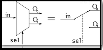
Schematic of a 2-to-1 Multiplexer. It can be equated to a controlled switch.
Schematic of a 1-to-2 Demultiplexer. Like a multiplexer, it can be equated to a controlled switch.
In electronics, a multiplexer or mux (occasionally the terms muldex or muldem are also found[1] for a combination multiplexer-demultiplexer) is a device that performs multiplexing; it selects one of many analog or digital input signals and forwards the selected input into a single line. A multiplexer of 2n inputs has n select lines, which are used to select which input line to send to the output.
An electronic multiplexer makes it possible for several signals to share one device or resource, for example one A/D converter or one communication line, instead of having one device per input signal.
On the other end, a demultiplexer (or demux) is a device taking a single input signal and selecting one of many data-output-lines, which is connected to the single input. A multiplexer is often used with a complementary demultiplexer on the receiving end.
An electronic multiplexer can be considered as a multiple-input, single-output switch, and a demultiplexer as a single-input, multiple-output switch. The schematic symbol for a multiplexer is an isosceles trapezoid with the longer parallel side containing the input pins and the short parallel side containing the output pin. The schematic on the right shows a 2-to-1 multiplexer on the left and an equivalent switch on the right. The sel wire connects the desired input to the output.
In telecommunications, a multiplexer is a device that combines several input information signals into one output signal, which carries several communication channels, by means of some multiplex technique. A demultiplexer is in this context a device taking a single input signal that carries many channels and separates those over multiple output signals.
In telecommunications and signal processing, an analog time division multiplexer (TDM) may take several samples of separate analogue signals and combine them into one pulse amplitude modulated (PAM) wide-band analogue signal. Alternatively, a digital TDM multiplexer may combine a limited number of constant bit rate digital data streams into one data stream of a higher data rate, by forming data frames consisting of one timeslot per channel.
In telecommunications, computer networks and digital video, a statistical multiplexer may combine several variable bit rate data streams into one constant bandwidth signal, for example by means of packet mode communication. An inverse multiplexer may utilize several communication channels for transferring one signal
Cost savings

The basic function of a multiplexer: combining multiple inputs into a single data stream. On the receiving side, a demultiplexer splits the single data stream into the original multiple signals.
One use for multiplexers is cost savings by connecting a multiplexer and a demultiplexer (or demux) together over a single channel (by connecting the multiplexer's single output to the demultiplexer's single input). The image to the right demonstrates this. In this case, the cost of implementing separate channels for each data source is more expensive than the cost and inconvenience of providing the multiplexing/demultiplexing functions. In a physical analogy, consider the merging behaviour of commuters crossing a narrow bridge; vehicles will take turns using the few available lanes. Upon reaching the end of the bridge they will separate into separate routes to their destinations.
At the receiving end of the data link a complementary demultiplexer is normally required to break single data stream back down into the original streams. In some cases, the far end system may have more functionality than a simple demultiplexer and so, while the demultiplexing still exists logically, it may never actually happen physically. This would be typical where a multiplexer serves a number of IP network users and then feeds directly into a router which immediately reads the content of the entire link into its routing processor and then does the demultiplexing in memory from where it will be converted directly into IP packets.
Often, a multiplexer and demultiplexer are combined together into a single piece of equipment, which is usually referred to simply as a "multiplexer". Both pieces of equipment are needed at both ends of a transmission link because most communications systems transmit in both directions.
A real world example is the creation of telemetry for transmission from the computer/instrumentation system of a satellite, space craft or other remote vehicle to a ground-based system.
In analog circuit design, a multiplexer is a special type of analog switch that connects one signal selected from several inputs to a single output.
Digital multiplexers
In digital circuit design, the selector wires are of digital value. In the case of a 2-to-1 multiplexer, a logic value of 0 would connect  to the output while a logic value of 1 would connect
  to the output. In larger multiplexers, the number of selector pins is equal to
  where
where  is the number of inputs.
For example, 9 to 16 inputs would require no fewer than 4 selector pins and 17 to 32 inputs would require no fewer than 5 selector pins. The binary value expressed on these selector pins determines the selected input pin.
A 2-to-1 multiplexer has a boolean equation where A and B are the two inputs,  is the selector input, and z is the output:


A 2-to-1 mux
Which can be expressed as a truth table:

This truth table shows that when  then
then  but when
  then
then  . A straightforward realization of this 2-to-1 multiplexer would need 2 AND gates, an OR gate, and a NOT gate.
Larger multiplexers are also common and, as stated above, requires  selector pins for n inputs. Other common sizes are 4-to-1, 8-to-1, and 16-to-1. Since digital logic uses binary values, powers of 2 are used (4, 8, 16) to maximally control a number of inputs for the given number of selector inputs.

The boolean equation for a 4-to-1 multiplexer iTwo realizations for creating a 4-to-1 multiplexer are shown below:

Two realizations for creating a 4-to-1 multiplexer are shown below:

- one realized from 3-state buffers and AND gates (the AND gates are acting as the decoder)
- Note that the subscripts on the
inputs indicate the decimal value of the binary control inputs at which that input is let through
Chaining multiplexers
Larger multiplexers can be constructed by using smaller multiplexers by chaining them together. For example, an 8-to-1 multiplexer can be made with two 4-to-1 and one 2-to-1 multiplexers. The two 4-to-1 multiplexer outputs are fed into the 2-to-1 with the selector pins on the 4-to-1's put in parallel giving a total number of selector inputs to 3, which is equivalent to an 8-to-1.
List of ICs which provide multiplexing
The 7400 series has several ICs that contain multiplexer(s):
S.No. | IC No. | Function | Output State |
1 | 74157 | Quad 2:1 mux. | Output same as input given |
2 | 74158 | Quad 2:1 mux. | Output is inverted input |
3 | 74153 | Dual 4:1 mux. | Output same as input |
4 | 74352 | Dual 4:1 mux. | Output is inverted input |
5 | 74151A | 8:1 mux. | Both outputs available (i.e., complementary outputs) |
6 | 74151 | 8:1 mux. | Output is inverted input |
7 | 74150 | 16:1 mux. | Output is inverted input |
Digital demultiplexers
Demultiplexers take one data input and a number of selection inputs, and they have several outputs. They forward the data input to one of the outputs depending on the values of the selection inputs. Demultiplexers are sometimes convenient for designing general purpose logic, because if the demultiplexer's input is always true, the demultiplexer acts as a decoder. This means that any function of the selection bits can be constructed by logically OR-ing the correct set of outputs.

List of ICs which provide demultiplexing
The 7400 series has several ICs that contain demultiplexer(s):
S.No. | IC No. | Function | Output State |
1 | 74139 | Dual 1:4 demux. | Output is inverted input |
3 | 74156 | Dual 1:4 demux. | Output is open collector |
4 | 74138 | 1:8 demux. | Output is inverted input |
5 | 74154 | 1:16 demux. | Output is inverted input |
6 | 74159 | 1:16 demux. | Output is open collector and same as input |
TOPOLOGY:
The physical topology of a network refers to the configuration of cables,computers and other peripherals
TYPES OF NETWORK TOPOLOGY:There are 3 types.mainly they are

- Bus
- Ring
- Star
- Tree
- Mesh
- BUS TOPOLOGY:
- All computers and devices connected to central cable or bus.
- Consists of a main run of cable with a terminator at each end.
- Popular on LAN’s because they are inexpensive and easy to install.

- RING TOPOLOGY:
- cable forms closed ring or loop with all computers and devices arranged along ring
- data travels from device to device around entire ring,in one direction.
- primarily is used for LAN’s but also is used in WAN’s.
- STAR TOPOLOGY:
- All devices connect to a central device,called a hub.
- all data transferred from one computer to another passes through hub.
- Tree topology:
tree topology integrate multiple star topologies together onto a bus.
In its simplest form, only hub devices connect directly to the tree bus, and each hub functions as the “root” of a tree devices.
This bus/star hybrid approach supports future expandability of the network much better than a bus or a star alone.
- MESH TOPOLOGY
Mesh topologies involve the concept of routes. Unlike each of the previous topologies, messages sent on a mesh network can take any of several possible paths from source to destination. (Recall that even in a ring, although two cable paths exist, messages can only travel in one direction.)
Some WAN’S, most notably the Internet, employ mesh routing.
A mesh network in which every device connects to every other is called a full mesh. As shown in the illustration below, partial mesh networks also exist in which some devices connect only indirectly to others.
Difference Between the three types of network topology:
bus
| Advantages | Disadvantages |
| Easy to connect computer or peripheral to a linear bus. | Entire network shut down if there is break in the main cable. |
| Requires less cable length than a star topology | Terminators are required at both ends of the backbone cable. |
| | Difficulty to identify the problem if the entire network shuts down. |
ring
| ADVANTAGES | DISADVANTAGES |
| Data is transferred with out a bottle neck | Data packets must pass through every computer between the sender and recipient therefore,this makes is slower. |
| The transmission of data relatively simple as packets travel in one direction only. | If any of the nodes fail then ring is broken and data cannot be transmitted successfully. |
| | It is difficult to troubleshoot the ring |
star
| ADVANTAGES | DISADVANTAGES |
| Easy to install and wire | Requires more cable length than a linear topology |
| security can be implemented | if the hub or concentrator fails,nodes attached are disabled |
| easy to detect faults and to remove parts | more expensive than a linear bus topologies because of the cost of the concentrators |
Subscribe to:
Posts (Atom)